

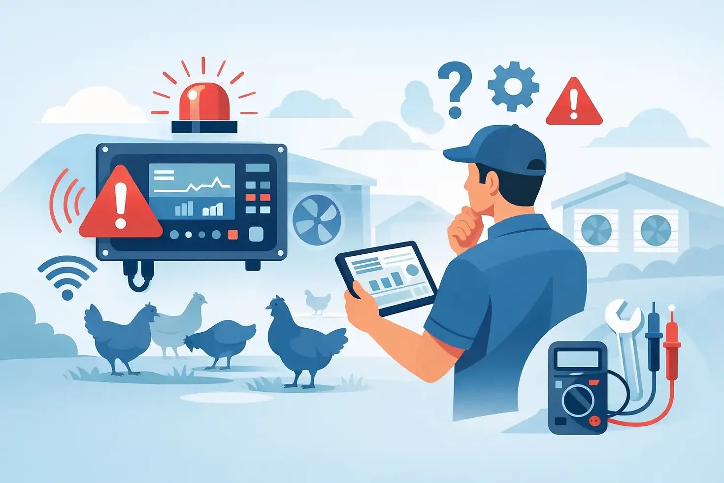
How to Troubleshoot Poultry Controller Alarms
A controller alarm at 2:00 a.m. is not automatically a controller failure. It may be reporting a real house condition, a failed input, a power issue, or an output that did not respond as commanded. To troubleshoot poultry controller alarms effectively, separate what the controller sees from what is actually happening in the house. That distinction prevents dangerous delays and avoids unnecessary component replacement.
For broiler, breeder, layer, pullet, and turkey operations, alarm response should protect flock conditions first. A technician can diagnose the source after ventilation, heating, cooling, and backup systems have been confirmed operational.
Start With the Alarm Type and House Condition
Read the complete alarm message before acknowledging or resetting it. Record the alarm type, house number, time, controller reading, current setpoint, and active equipment status. This information is especially valuable when the alarm has cleared by the time someone arrives at the barn.
Then verify the house independently. Use a reliable handheld thermometer or meter to compare air temperature, relative humidity, carbon dioxide concentration, or static pressure with the displayed controller value. Check bird behavior as well. Bird distribution, panting, huddling, and movement toward or away from inlets often reveal a developing environmental problem before one screen value does.
An alarm can be valid even when the house does not feel extreme at the door. Temperature can stratify, tunnel ventilation can be uneven, and a sensor located near a cold wall, heater discharge, inlet, or direct airflow can report conditions that are not representative of the bird zone. Inspect the sensor location as part of the diagnosis.
Treat Critical Environmental Alarms as Real Until Proven Otherwise
High temperature, low temperature, ventilation failure, high carbon dioxide, and power failure alarms require immediate action. Do not begin with alarm settings. First, confirm that the equipment needed to stabilize the house is available and operating.
For a high-temperature alarm, verify that the correct fan stages are running, cooling equipment is enabled when conditions call for it, inlets are moving, and the house has adequate air exchange. Check fan belts, breakers, contactors, motor overloads, phase loss protection, and shutters. A controller may be sending the correct output while the fan circuit, motor, or mechanical equipment fails downstream.
For a low-temperature alarm, confirm heater fuel supply, ignition, safety lockouts, circulation fans, and minimum ventilation operation. A heater that cycles correctly at one end of a house may not deliver adequate heat through the full bird area. Check the controller's temperature sensor against a handheld reference before changing heating parameters.
High carbon dioxide or static pressure alarms often point to a ventilation problem rather than a sensor problem. Confirm fan operation, inlet travel, actuator response, air leaks, dirty pads or filters where applicable, and closed doors or curtains. In a tight house, one stuck inlet or failed actuator can create poor air distribution while total fan runtime appears normal.
Check Sensors Before Changing Setpoints
Sensors are the controller's view of the house. If that view is incorrect, the controller can make the wrong decision while operating exactly as programmed.
Compare the controller reading with an independent instrument placed near the sensor location. Allow sufficient time for the handheld instrument to stabilize. A quick comparison made immediately after walking into a warm or cold house can be misleading.
Inspect the sensor cable, connector, and terminal block for loose connections, corrosion, moisture intrusion, rodent damage, or pinched wiring. Look for sensor contamination as well. Dust, feathers, washdown residue, and insect buildup can affect humidity, carbon dioxide, and static pressure measurements. Pressure tubing should be dry, intact, connected to the correct ports, and free of kinks or blockage.
A sudden jump to an implausible value usually suggests an input, cable, or sensor fault. A gradual difference between the controller and a trusted reference may indicate drift, placement issues, or calibration requirements. Replace or recalibrate components according to the sensor specification rather than compensating with a permanent setpoint adjustment.
Do not use alarm limits to hide a suspect sensor. Widening a high-temperature or CO2 threshold may stop nuisance notifications, but it also removes protection when a real event occurs.
Verify Outputs, Not Just the Screen
When an alarm is tied to ventilation, feeding, weighing, or another controlled function, check whether the controller output is active. An active output indicator confirms the controller has issued a command. It does not prove that the connected equipment is running.
Trace the path from the controller output to the final device. Depending on the installation, that can include an output module, relay, contactor, overload, variable-speed drive, motor starter, breaker, fuse, field wiring, and the equipment itself. A failed contactor coil, tripped overload, loose neutral, or damaged motor cable can stop equipment even though the controller command is correct.
The opposite condition also occurs. Equipment may continue running when the controller output is off because of a welded relay, failed contactor, manual override, or incorrect field wiring. This can create low-temperature, excess ventilation, feed delivery, or static pressure alarms that appear to be programming problems.
Use qualified electrical personnel for live-panel diagnostics. Lockout and tagout procedures remain necessary when inspecting motors, augers, fans, and other mechanically energized equipment.
Check Manual Overrides and Service Modes
Manual overrides are useful during maintenance but commonly create confusing alarm events. Verify the position of local hand-off-auto switches, breaker-mounted controls, VFD local control settings, and any temporary bypasses. A fan placed in manual operation may run continuously regardless of controller output, while a device left off can cause repeated alarm conditions.
Also confirm whether the controller is in a service, cleaning, empty-house, or special operating program. Alarm behavior, ventilation timing, and active setpoints may be different from normal flock operation.
Review the Program Against the Current Flock Stage
Many recurring alarms are configuration issues. Confirm that the selected house program matches the flock type, bird age, target weight, season, and current production phase. Minimum ventilation requirements, temperature curves, humidity limits, cooling activation points, and alarm delays should reflect current conditions, not last flock's setup.
Alarm delays deserve careful review. A delay that is too short can create notifications during normal equipment transitions, such as fan staging or heater recovery. A delay that is too long can postpone action during a genuine ventilation or temperature failure. The correct value depends on house design, equipment capacity, bird density, and how quickly conditions can change.
Check sensor assignments and output mappings after software updates, controller replacement, module expansion, or electrical modifications. A temperature sensor assigned to the wrong zone, or a fan output linked to an incorrect stage, can produce alarms that are difficult to explain from the house floor.
For connected control systems such as the Columbus AGM platform, verify that remote monitoring reflects the local controller state. A communication loss alarm can be a network, router, antenna, power supply, or controller communication issue rather than a climate-control failure. Local operation should be checked independently before focusing on remote access.
Investigate Power and Communication Alarms Systematically
A power alarm may indicate a complete outage, a brief voltage interruption, a lost phase, a failed backup supply, or a monitoring circuit fault. Check the main service, generator status, transfer switch, distribution panels, controller supply voltage, and backup battery condition where installed. Review timestamps to determine whether the controller rebooted or simply reported an external power event.
Intermittent events require more than a single visual inspection. Loose terminals, weak batteries, voltage drop under fan load, nuisance breaker trips, and failing contactors often appear only when equipment starts. Document the time and equipment state for each occurrence so patterns can be identified.
For communication alarms, inspect network power and physical connections first. Then confirm controller communication settings, signal quality where wireless equipment is used, and the status of other connected devices. Avoid repeatedly resetting the controller before collecting alarm history. A reset can remove evidence needed to identify an intermittent fault.
Test the Alarm Path After the Repair
A repair is incomplete until the alarm path has been tested. Confirm that the controller recognizes the restored input or output condition, that the local audible or visual alarm operates as configured, and that remote notification reaches the responsible person when applicable.
Test only under controlled conditions that do not compromise bird welfare. A qualified technician can simulate an input condition, use approved test functions, or verify alarm relay operation without shutting down essential ventilation. Record the result, corrective action, replacement parts, and any parameter changes in the house service log.
The best alarm response is repeatable: verify the birds and environment, identify whether the issue is input, control logic, output, or power, then prove the system works after correction. That discipline keeps a nuisance alarm from becoming a production event and keeps a real warning from being dismissed as noise.


Comments